How a Drone Argues With Gravity
A beginner-friendly walkthrough of PID control: target, error, P, I, D, cascaded loops, feedforward, and motor mixing in a drone simulator.
At the end of last post the drone finally had a decent idea of which way was up. The MEKF took noisy gyro and accelerometer readings and turned them into one orientation estimate.
That is useful, but it is still not flying.
Knowing “I am tilted 5 degrees” does not automatically fix the tilt. Something has to look at the current state, compare it to the target, and decide what the motors should do next. That something is the controller.
So this post is about the controller in my drone sim. Not in a fancy way. Just the basic loop:
- Where do I want to be?
- Where am I right now?
- What motor command should reduce that gap?
That loop runs 200 times a second. Each pass is small, but together those tiny corrections are what keep the drone from drifting, sagging, or tipping over.
Where we are in the series. Frames, quaternions, dynamics, sensors, and estimation. Today we add the part that chooses the motor commands. I will start with the basic idea of error, then build up to PID, cascaded loops, and motor mixing.
Start With Error
A controller starts with one simple number:
If I want the drone at 3 meters, and it is currently at 2.4 meters, the altitude error is 0.6 meters. It is too low.
If it is currently at 3.2 meters, the error is -0.2 meters. It is too high.
That is the basic idea. A controller does not need to “understand” flying in a human way. It just keeps asking: how far am I from where I want to be, and what should I do to make that error smaller?
This sounds almost too simple, but most of control starts here.
The First Bad Idea: Full On Or Full Off
The most obvious controller is:
- if the drone is too low, turn the motors up
- if the drone is too high, turn the motors down
That is called bang-bang control. It only has two moods: full push one way, full push the other way.
You have probably felt this in a bad shower. The water is too cold, so you turn the hot tap a lot. Nothing happens for a second, so you turn it more. Then the hot water arrives all at once, it is too hot, and you yank it back. Then it gets cold again. You keep overshooting because the control is too rough.
A drone would do the same thing. It would blast upward, pass the target height, cut power, fall back down, then blast upward again. It would not settle nicely.
So we need something smoother than “full on” and “full off”.
PID: Three Ways To Use The Error
PID stands for Proportional, Integral, Derivative.
That name sounds bigger than the idea. PID just means we look at the error in three different ways:
- P asks: how wrong am I right now?
- I asks: how long have I been wrong?
- D asks: how fast am I moving toward or away from the target?
Then we add those three answers together.
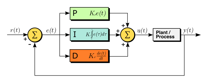 the basic PID loop. the target and current value make an error. P, I, and D each look at that error differently, and their sum becomes the command. figure by Arturo Urquizo, Wikimedia Commons, CC BY-SA 3.0

Here is the whole thing in my code:
1
2
3
def step(self, error, rate, dt):
    self._i = clamp(self._i + error * dt, -self.i_limit, self.i_limit)
    return self.kp * error + self.ki * self._i - self.kd * rate
The three knobs are kp, ki, and kd.
kpdecides how strongly P reacts to the current error.kidecides how strongly I reacts to error that has been sitting there for a while.kddecides how strongly D brakes motion.
Tuning a PID controller mostly means choosing those three numbers.
P: Push In Proportion To The Error
The P term is the easiest one.
If the error is big, push hard. If the error is small, push gently.
For altitude, a simple P controller might say:
So if the drone is far below the target, it adds a lot of thrust. If it is only a little below, it adds a little thrust.
That already feels much better than bang-bang control. But P alone has two problems.
First, if kp is too small, the drone reacts slowly.
Second, if kp is too large, the drone rushes past the target and starts bouncing around it.
This is the usual tradeoff:
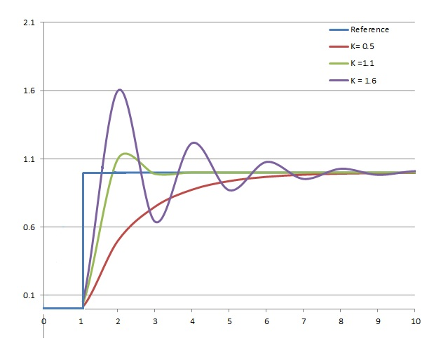 same system, different gains. low gain is calm but slow. high gain is fast but overshoots and rings. plot by TimmmyK, Wikimedia Commons, public domain
There is also a drone-specific issue: gravity.
Gravity is always pulling down. For my half-kilo drone, the hover thrust is about 4.9 newtons. A pure P controller can create that thrust only if there is still some height error left.
Here is the tiny bit of math.
- z is the current height.
- zd is the desired height.
- Kp is the P gain.
- F is thrust.
- mg is the drone’s weight.
A pure P altitude controller says:
To hover, thrust has to equal weight:
So at hover:
Which means:
That leftover error is the important part. P alone needs some error to produce the thrust that holds the drone up. So in this simple picture, the drone sits a little below the target instead of exactly on it.
That is why P is useful, but not enough.
D: Brake Before You Overshoot
The D term is the brake.
Imagine the drone is below the target and moving upward fast. The P term still sees “I am too low” and wants to push upward. But if the drone is already rushing upward, pushing harder is a bad idea. It will overshoot.
D looks at the rate, meaning how fast the value is changing. For altitude, that rate is vertical speed. For attitude, it is angular speed.
So D says: if we are already moving quickly, push back a bit.
In the attitude loop, the command looks like this:
The minus sign matters. It means D opposes the motion. If the drone is rotating too quickly toward the target, D slows it down before it flies past.
This is why people say D adds damping. It makes the motion less bouncy.
There is a real second-order-system formula behind this:
You do not need to memorize it. The point is simpler: for the same P gain, adding more D usually makes the system less bouncy. Too little D rings. Too much D feels sluggish.
That is the intuition I actually use while tuning.
I: Fix Error That Refuses To Go Away
The I term is slower.
It adds up error over time:
This helps when there is a small error that never disappears.
Altitude is the clean example. Gravity is a constant load. If the drone keeps sitting a little below the target, the I term keeps adding that leftover error. Slowly, it adds enough extra thrust to remove the sag.
That is why my altitude loop has an integral term:
1
2
3
self.pid_z = PID(kp=6.0, ki=0.3, kd=4.0)   # has I
self.pid_x = PID(kp=0.5, ki=0.0, kd=1.5)   # no I
self.pid_y = PID(kp=0.5, ki=0.0, kd=1.5)   # no I
In this simple no-wind simulator, gravity is the main constant load, and it shows up on the z axis. So z gets ki. The x and y loops do not need it here.
On real hardware, you might add integral in more places because of wind, motor imbalance, or frame misalignment. I am not saying “only altitude ever needs I”. I am saying this sim has a simple reason for where I used it.
Two Practical Details That Matter
The clean PID diagram is useful, but real code needs two small protections.
Derivative On Measurement
The textbook D term is often written as “derivative of the error”.
The problem is that the target can jump. If the target height changes from 1 meter to 3 meters, the error jumps instantly, even though the drone itself did not suddenly move. If we differentiate that error, D sees a fake huge speed and sends a bad spike to the motors.
So my code does this instead:
1
return self.kp * error + self.ki * self._i - self.kd * rate
I pass in the measured rate directly. The drone’s real speed does not teleport when the target changes, so this avoids the spike.
That is called derivative on measurement.
Anti-Windup
The I term can also cause trouble.
Imagine the motors are already at their limit, but the drone still cannot reach the target. The error stays there, so the integral keeps growing and growing. Later, when the drone can move again, that stored-up integral can shove it too far.
That is called integral windup.
The simple fix is to cap the accumulated integral:
1
self._i = clamp(self._i + error * dt, -self.i_limit, self.i_limit)
So the integral can help, but it cannot grow without limit.
One PID Loop Is Not Enough
A quadrotor cannot directly move sideways.
There is no “move right” motor. To move right, the drone has to tilt, which points part of its thrust sideways. So position control becomes two smaller problems:
- The outer loop asks: what tilt would move me toward the target?
- The inner loop asks: what motor torques will create that tilt?
This is called cascaded control.
- The outer loop looks at position error and outputs a desired tilt.
- The inner loop looks at attitude error and outputs torques.
In code, it looks like this:
1
2
3
4
5
6
# OUTER: position error -> desired tilt
ax_d = self.pid_x.step(xd - p.x, v.x, DT)
pitch_d = clamp(ax_d / GRAVITY, -0.35, 0.35)

# INNER: attitude error -> torque
tau_y = self.pid_pitch.step(pitch_d - pitch, wb.y, DT)
The output of the outer loop becomes the target for the inner loop.
The inner loop has to be faster. If the position loop asks for a tilt, the attitude loop should make that tilt happen quickly. Otherwise the position loop keeps changing its mind before the attitude loop catches up, and the drone starts behaving badly.
In my sim both loops run in the same 200 Hz callback. The speed difference comes mostly from tuning: the attitude loop is made more aggressive than the position loop, so attitude settles faster than position.
Why Sideways Acceleration Becomes Tilt
This line is the bridge between the outer and inner loops:
1
pitch_d = clamp(ax_d / GRAVITY, -0.35, 0.35)
The outer loop asks for sideways acceleration ax_d. But the inner loop needs a pitch angle. So why divide by gravity?
Here is the basic geometry.
When a drone is level, all thrust points upward. When it tilts by angle θ, the thrust tilts too. Now the thrust has two parts:
- one part still points upward and holds the drone up
- one part points sideways and accelerates the drone sideways
For small tilt angles:
So:
That is all this line is doing:
1
pitch_d = ax_d / GRAVITY
The clamp(..., -0.35, 0.35) keeps the tilt around 20 degrees or less. That keeps the small-angle shortcut reasonable, and it also stops the drone from tilting so far that it loses too much upward thrust.
Gravity Feedforward
Now look at the altitude command:
1
F = MASS * GRAVITY + self.pid_z.step(zd - p.z, v.z, DT)
The first part is:
1
MASS * GRAVITY
That is the thrust needed just to hover level. It is the baseline.
Then the PID term adds or subtracts from that baseline:
- need to climb? add more thrust
- need to descend? add less thrust
- already at the right height? stay near the hover thrust
This is called feedforward. It means we give the controller something we already know, instead of making PID discover it slowly.
Without this line, the integral term could eventually learn the hover thrust, but the drone would sag first and respond worse. Feedforward just starts the controller closer to the right answer.
Turning Thrust And Torque Into Motor Speeds
At this point the controller knows what it wants:
- total thrust F
- roll torque τx
- pitch torque τy
- yaw torque τz
But the drone cannot directly set “thrust” or “torque”. It can only set four motor speeds.
So we need motor mixing. This is the inverse of the mixing matrix from the dynamics post.
In the dynamics post, we asked:
Given four motor speeds, what force and torques do they create?
Now the controller asks the opposite:
Given the force and torques I want, what motor speeds should I use?
The code is:
1
2
3
4
5
6
7
8
def motor_mixing(F, tau_x, tau_y, tau_z):
    w_sq = [
        F/(4*KT) - tau_y/(2*KT*L) - tau_z/(4*KQ),   # M1
        F/(4*KT) + tau_x/(2*KT*L) + tau_z/(4*KQ),   # M2
        F/(4*KT) + tau_y/(2*KT*L) - tau_z/(4*KQ),   # M3
        F/(4*KT) - tau_x/(2*KT*L) + tau_z/(4*KQ),   # M4
    ]
    return [math.sqrt(max(0.0, w)) for w in w_sq]
The F/(4*KT) part appears in every motor because total thrust is shared across all four motors.
The torque terms add to some motors and subtract from others. That imbalance is how the drone rolls, pitches, and yaws.
The sqrt at the end is there because propeller thrust grows with speed squared. The mixer first solves for speed squared, then takes the square root to get motor speed.
The Gains Were Not Magic
The structure above is principled. The actual numbers still came from tuning.
These values:
1
2
3
kp=6.0
ki=0.3
kd=4.0
were not handed to me by the math. I ran the sim, watched what happened, and adjusted them.
But the math tells you which direction to adjust:
- drone sags below target? increase
kior add hover feedforward - drone overshoots and rings? increase
kdor lowerkp - drone feels slow? increase
kp
So tuning is still trial and error, but it is not random.
Wrap Up
The controller is the part that turns estimates into action.
- Start with error: target minus current value.
- P reacts to the current error.
- D brakes motion so the drone does not overshoot as much.
- I handles errors that stay around for a long time.
- Derivative on measurement avoids a spike when the target jumps.
- Anti-windup stops the integral from growing too much.
- Cascaded control lets the position loop ask for tilt, and the attitude loop make that tilt happen.
- Feedforward gives the controller the known hover thrust up front.
- Motor mixing turns desired thrust and torques into four motor speeds.
That closes the loop: estimation tells the drone where it is, PID decides what correction is needed, and motor mixing turns that correction into motor commands.
Next step would be tuning it better, or testing how it behaves when the target moves around.
Further Reading
- Brett Beauregard, Improving the Beginner’s PID, a very clear practical PID series.
- Astrom and Murray, Feedback Systems, the more rigorous textbook version, if you want the deeper math.
Thanks for reading. If I got a controller detail wrong pls ping me on X and I will fix it.