What Does It Take to Fake a Flying Drone?
Newton-Euler dynamics, motor mixing and RK4 integration, the complete physics loop inside my quadrotor simulator, taught from scratch.
Here is a thing that surprised me when I built my drone simulator: the entire physics, everything that makes the drone climb, tilt, drift and crash, lives in one function. It is about 30 lines long. The simulator calls it 200 times per second and that’s it, that is the whole “physics engine”.
The function answers exactly one question: given where the drone is right now and how fast its four motors are spinning, how is everything changing at this instant? Answer that, and the rest is just bookkeeping.
In this post I want to build that function from scratch with you. We will start from “what does a propeller even do” and end at the actual C++ that runs in my sim. No step skipped. It’s a long one, but if you have followed the first two posts you already have all the tools you need.
Quick recap of where we are. Post one was about coordinate frames, the world frame is glued to the ground and the body frame is glued to the drone. Post two was about quaternions, the 4 numbers we use to track how the body frame is oriented relative to the world frame. Today both of those finally get used for their actual job: simulating flight.
The 13 Numbers That Fully Describe a Flying Drone
Before any physics, we need to agree on what we are keeping track of. Here is the state struct from my simulator:
1
2
3
4
5
6
struct QuadState {
    double px, py, pz;      // position, world frame (m)
    double vx, vy, vz;      // velocity, world frame (m/s)
    double qw, qx, qy, qz;  // attitude quaternion, body -> world
    double wx, wy, wz;      // angular rate, body frame (rad/s)
};
Thirteen numbers. That is everything. If you know these 13 numbers you know everything about the drone at this moment:
| numbers | what they are | which frame | answers the question |
|---|---|---|---|
px, py, pz | position | world | where is it ? |
vx, vy, vz | velocity | world | where is it heading ? |
qw, qx, qy, qz | orientation quaternion | body to world | which way is it tilted ? |
wx, wy, wz | angular velocity | body | how fast is it spinning ? |
(Well, everything my model cares about. A real drone hides more state than this, motors take time to spin up, the battery sags, the frame flexes, wind shoves things around. A rigid body model ignores all of that on purpose, and for learning flight control it is the right trade.)
Why 13 and not 12? A drone has 6 degrees of freedom (3 for position, 3 for orientation) so with velocities that is 12 numbers of actual freedom. But as we saw in the last post, we store orientation as a quaternion, which uses 4 numbers plus one constraint ($|\mathbf{q}| = 1$) to describe 3 degrees of freedom. So 13 numbers, 1 constraint, 12 true degrees of freedom.
Notice the frames, this trips everyone up at first. Position and velocity live in the world frame because that’s what we care about (“the drone is 3 meters up”). Angular velocity lives in the body frame because that’s what the gyroscope physically measures, the gyro is bolted to the drone, it can only feel rotation about its own axes.
Physics Is Just a Rule for Change
Here is the mental model that made all of this click for me. A simulator does not need to know the future. It only needs one rule:
\[\dot{\mathbf{x}} = f(\mathbf{x}, \text{motors})\]In words: give me the current state $\mathbf{x}$ (our 13 numbers) and the current motor speeds, and I will tell you the rate of change of every single one of those 13 numbers right now. How fast is position changing? How fast is velocity changing? How fast is the quaternion changing?
This kind of rule is called a differential equation. It just says “here is how fast things are changing, you figure out where they end up”. The “figure out where they end up” part is called integration and we will deal with it at the end of the post.
So our whole job is to write the function $f$. In my code it is called qd_derivative, and here is its signature:
1
QuadState qd_derivative(const QuadState &s, const std::array<double,4> &omega)
Two inputs and one output, and since they show up in every code block below, let me name them once so nothing is mysterious later:
sis the current state, the 13 numbers from the struct above. Sos.qwmeans “the qw field of the current state” (the w component of the orientation quaternion right now),s.vxis the current x velocity,s.wxis the current roll rate, and so on. The dot is just C++ for reaching inside a struct.omegais the array of 4 motor speeds.omega[0]is motor 1,omega[1]is motor 2, etc (C++ arrays count from zero).dis what we return, anotherQuadState, but here every field holds a rate of change instead of a value. Sod.pxis how fast position x is changing,d.vxis the x acceleration,d.qwis how fast the quaternion’s w component is changing. Same struct shape ass, completely different meaning.
Hold onto that one distinction, s is the value right now and d is how fast it is changing, and the rest of the code reads easily. Let’s build the function piece by piece.
What Does One Spinning Propeller Actually Do?
Two things. Both of them are Newton’s third law (every action has an equal and opposite reaction) doing its thing.
Thing 1: thrust. The propeller is shaped so that when it spins, it grabs air from above and throws it downward. The prop pushes air down, so the air pushes the prop up. That upward push is thrust.
How much thrust? The blades move through the air at a speed proportional to how fast the motor spins, and the lift a blade generates grows with the square of how fast it moves through air. So:
\[T = K_T\, \omega^2\]where $\omega$ is the motor speed in rad/s and $K_T$ is a constant that bundles up air density, propeller size and blade shape into one number. Double the motor speed, four times the thrust. (Real propellers have more going on, but this quadratic model is the standard simplification and it is plenty good for a simulator.)
Thing 2: reaction torque. This one is sneakier. To keep the prop spinning against air resistance, the motor has to keep twisting it. But by Newton’s third law, if the motor twists the prop one way, the prop twists the motor, and the whole drone body it is bolted to, the other way.
\[\tau_{drag} = K_Q\, \omega^2\]So a propeller spinning counterclockwise constantly tries to spin the drone body clockwise. This is not some small ignorable effect, it is exactly the reason single-rotor helicopters need a tail rotor. Without it the helicopter body would just spin opposite to the main blade.
Quadrotors solve this much more elegantly, and that’s the next section.
The Constants in My Sim
My simulator models a DJI F450-class quad, the constants live in quad_dynamics.hpp:
1
2
3
4
5
6
7
8
inline constexpr double QD_MASS    = 0.5;       // kg
inline constexpr double QD_GRAVITY = 9.81;      // m/s^2
inline constexpr double QD_L       = 0.17;      // arm length, m
inline constexpr double QD_KT      = 3.13e-5;   // thrust coefficient
inline constexpr double QD_KQ      = 7.5e-7;    // drag torque coefficient
inline constexpr double QD_IXX     = 2.3e-3;    // moment of inertia, x
inline constexpr double QD_IYY     = 2.3e-3;    // moment of inertia, y
inline constexpr double QD_IZZ     = 4.5e-3;    // moment of inertia, z
Don’t worry about the inertia numbers yet, they get their own section. The fun one right now is $K_T$, because it lets us do our first sanity check.
How fast must the motors spin to hover? Hovering means total thrust exactly cancels gravity. Four motors all spinning at the same speed $\omega_h$:
\[4\, K_T\, \omega_h^2 = m g\] \[\omega_h = \sqrt{\frac{m g}{4 K_T}} = \sqrt{\frac{0.5 \times 9.81}{4 \times 3.13 \times 10^{-5}}} \approx 197.9 \text{ rad/s}\]And in the header:
1
inline constexpr double QD_W_HOVER = 197.92;   // rad/s  (pre-computed)
There it is. About 1890 RPM. When the simulator starts, all four motors get set to exactly this value, which is why the drone just sits there hovering until the controller tells it otherwise.
The Plus Layout: Four Speeds In, Four Forces Out
Here is how the motors are arranged in my sim, viewed from above. Body x points out the nose, body y points left, body z up toward you out of the screen:
1
2
3
4
5
6
7
8
9
10
11
                      front (+x)
                         M1
                       (CCW)
                         |
                         |
   left (+y)  M2 --------+-------- M4
             (CW)        |        (CW)
                         |
                         M3
                       (CCW)
                        back
This is called the plus configuration, the nose points straight along one arm so the frame looks like a + flying forward. (The other common layout is the X configuration where the nose points between two arms, racing drones mostly use that one, the math is the same with a rotated mixing matrix.) Two things to memorize here: motors 1 and 3 sit on the x axis and spin counterclockwise, motors 2 and 4 sit on the y axis and spin clockwise.
Why opposite spins? Remember the reaction torque from the last section. The two CCW props push the body clockwise, the two CW props push the body counterclockwise. At hover all four torques cancel perfectly and the drone holds its heading. No tail rotor needed, the quad is its own tail rotor.
Now the magic part. We have 4 motor speeds we can choose freely, and it turns out that gives us exactly 4 independent “controls”: total thrust and three torques. Let’s go through them one at a time.
Total thrust is the easy one, just add up all four:
\[T = K_T\,(\omega_1^2 + \omega_2^2 + \omega_3^2 + \omega_4^2)\]Roll torque (rotation about the x axis, tipping left or right). Torque is force times lever arm, the same reason a longer wrench loosens a stuck bolt more easily. Motors 2 and 4 sit a distance $L$ from the center on the y axis, so any thrust difference between them twists the body about x:
\[\tau_x = K_T L\,(\omega_2^2 - \omega_4^2)\]Speed up M2 (left motor), slow down M4 (right motor): the left side gets pushed up harder, the drone tips toward its right. Total thrust unchanged if you speed one up exactly as much as you slow the other down.
Pitch torque (rotation about the y axis, nose up or down). Same trick with the other pair:
\[\tau_y = K_T L\,(\omega_3^2 - \omega_1^2)\]Speed up M3 (back motor), slow down M1 (front motor): the back lifts, the nose drops, and now the thrust vector leans forward so the drone accelerates forward. This is exactly the “tilt to move” thing from post one, and now you know precisely which motors make it happen.
Yaw torque (rotation about the z axis, swinging the nose left or right). This is the clever one, because notice that motors 1 and 3 are both on the x axis, you cannot create yaw with thrust differences. Instead yaw comes entirely from those reaction drag torques:
\[\tau_z = K_Q\,(-\omega_1^2 + \omega_2^2 - \omega_3^2 + \omega_4^2)\]The signs follow the spin directions. M1 and M3 spin CCW so their reaction pushes the body CW (negative sign), M2 and M4 spin CW so their reaction pushes the body CCW (positive sign). Speed up the CW pair and slow the CCW pair by the same amount: thrusts stay balanced, the drone stays level, total lift unchanged, but the reaction torques no longer cancel and the nose swings counterclockwise. The drone always turns opposite to the props you sped up, which I find weirdly pleasing.
Here is the whole thing in code, the first few lines of qd_derivative:
1
2
3
4
5
6
7
double w2[4] = {omega[0]*omega[0], omega[1]*omega[1],
                omega[2]*omega[2], omega[3]*omega[3]};

double thrust = QD_KT * (w2[0] + w2[1] + w2[2] + w2[3]);
double tau_x  = QD_KT * QD_L * ( w2[1] - w2[3]);
double tau_y  = QD_KT * QD_L * ( w2[2] - w2[0]);
double tau_z  = QD_KQ        * (-w2[0] + w2[1] - w2[2] + w2[3]);
(Arrays in C++ are zero-indexed so w2[0] is motor 1, w2[1] is motor 2 and so on.)
One more way to look at this that I really like: it is a matrix. Four knobs in, four outputs out, connected by a fixed 4x4 linear map:
\[\begin{bmatrix} T \\ \tau_x \\ \tau_y \\ \tau_z \end{bmatrix} = \begin{bmatrix} K_T & K_T & K_T & K_T \\ 0 & K_T L & 0 & -K_T L \\ -K_T L & 0 & K_T L & 0 \\ -K_Q & K_Q & -K_Q & K_Q \end{bmatrix} \begin{bmatrix} \omega_1^2 \\ \omega_2^2 \\ \omega_3^2 \\ \omega_4^2 \end{bmatrix}\]This is called the motor mixing matrix. It is square and invertible, which matters a lot, because the controller has the opposite problem: it decides “I want this much thrust and these torques” and needs to work backward to motor speeds. That inverse lives in my PID controller and it will get its own post.
Newton’s Half: How Position and Velocity Change
Forces sorted, now we can do actual physics. The translation part is governed by the most famous equation there is:
\[\mathbf{F} = m\mathbf{a} \quad\Rightarrow\quad \mathbf{a} = \frac{\mathbf{F}}{m}\]Add up every force on the drone, divide by mass, that’s the acceleration. There are exactly two forces in my sim:
- Gravity. Always $(0, 0, -mg)$ in the world frame, no matter what the drone is doing. Easy.
- Thrust. Always $(0, 0, T)$ in the body frame, the props can only push along the drone’s own up axis.
And there is the catch: one force lives in the world frame, the other in the body frame. You cannot add vectors that live in different frames, that’s like adding rupees to dollars without converting. So we rotate the thrust into the world frame first, using the quaternion sandwich from last post:
1
2
double fx, fy, fz;
qd_quat_rot(s.qw, s.qx, s.qy, s.qz, 0.0, 0.0, thrust, fx, fy, fz);
Note there are no minus signs on the quaternion this time. In the first post we used this same helper with the conjugate (all the minus signs) to rotate world gravity into the body frame for the fake accelerometer. Here we use the quaternion as-is, body to world, to push thrust out into the world frame. Same function, both directions, depending on whether you conjugate.
If the drone is level, $(0,0,T)$ stays pointing straight up and all the thrust fights gravity. If the drone pitches forward 30 degrees, the rotation smears that vector into something like $(0.5\,T, 0, 0.87\,T)$, suddenly half a T of force is pulling the drone forward. Tilting is steering. This is the entire reason drones tilt to move.
Now the derivatives:
1
2
3
4
5
6
QuadState d;
d.px = s.vx;  d.py = s.vy;  d.pz = s.vz;

d.vx = fx / QD_MASS;
d.vy = fy / QD_MASS;
d.vz = fz / QD_MASS - QD_GRAVITY;
First line: the rate of change of position is velocity, that is literally the definition of velocity, nothing deep happening.
Next three lines: acceleration = force over mass. Gravity gets subtracted only from the z component, because in the world frame gravity only ever points down, that’s the whole point of doing this math in the world frame.
That’s Newton’s half done. Six of our 13 derivatives, in six lines.
Euler’s Half: How Rotation Changes
Rotation needs its own version of $F = ma$, and it was Euler (yes, the same Euler, the man is everywhere) who worked it out. The rotational analogue swaps every ingredient:
| translation | rotation |
|---|---|
| force $\mathbf{F}$ | torque $\boldsymbol{\tau}$ |
| mass $m$ | moment of inertia $I$ |
| acceleration $\mathbf{a}$ | angular acceleration $\dot{\boldsymbol{\omega}}$ |
Moment of Inertia, the Rotational Mass
Mass measures how hard it is to push something. Moment of inertia measures how hard it is to spin something. And unlike mass it is not one number, it depends on which axis you spin around, because what matters is not just how much mass there is but how far that mass sits from the axis.
Try this with a water bottle: spin it around its long axis (easy, mass is close to the axis) versus flipping it end over end (harder, mass is far from the axis). Same bottle, same mass, different moment of inertia per axis.
Now look at my drone’s numbers again:
1
2
3
inline constexpr double QD_IXX = 2.3e-3;   // roll axis
inline constexpr double QD_IYY = 2.3e-3;   // pitch axis
inline constexpr double QD_IZZ = 4.5e-3;   // yaw axis
$I_{zz}$ is almost exactly double $I_{xx}$. I stared at that for a while before it clicked, and the explanation is honestly satisfying. The heavy things on a quad are the four motors sitting at distance $L$ from the center. Count which motors are far from each axis:
- x axis (the M1-M3 arm): motors 1 and 3 sit on this axis, distance zero, they contribute nothing. Only motors 2 and 4 are far from it. Two motors count.
- z axis (pointing up through the center): all four motors are at distance $L$ from it. Four motors count.
Four versus two. $I_{zz} \approx 2\, I_{xx}$. The numbers in the header are not arbitrary, the geometry is hiding inside them.
(Practical consequence: yaw is the sluggish axis on a quad. Twice the inertia, and the yaw torque comes from the weak $K_Q$ drag effect instead of strong thrust differences. If you have flown one you have felt this, roll and pitch are snappy, yaw is lazy.)
Euler’s Rotation Equation
Here is the rotational $F = ma$, written in the body frame:
\[I\,\dot{\boldsymbol{\omega}} = \boldsymbol{\tau} - \boldsymbol{\omega} \times (I\boldsymbol{\omega})\]The $I\dot{\boldsymbol{\omega}} = \boldsymbol{\tau}$ part is exactly what you would guess from the table above: torque over inertia gives angular acceleration, the rotational copy of $a = F/m$. The mystery is that extra term, $\boldsymbol{\omega} \times (I\boldsymbol{\omega})$, which has no equivalent on the translation side at all. It is called the gyroscopic term, and it is the one genuinely weird thing in this whole post, so let me build it up slowly. It comes from two simple facts crashing into each other.
Fact 1: spin and momentum do not always point the same way.
For motion in a straight line, momentum is $m\mathbf{v}$. Mass is a single number, so momentum always points the same direction as velocity. Nice and simple.
Rotation is sneakier, because the rotational “mass” $I$ is not a single number, it is different along each axis (that whole $I_{xx}$ vs $I_{zz}$ thing from a moment ago). Angular momentum is $I\boldsymbol{\omega}$, and when you multiply a vector by something that stretches each axis by a different amount, the result generally points in a different direction than the vector you started with.
So spin $\boldsymbol{\omega}$ and momentum $I\boldsymbol{\omega}$ only line up perfectly when you rotate about one of the drone’s clean axes (pure roll, pure pitch, or pure yaw). Rotate about a tilted, in-between axis and the momentum vector leans away from the spin vector, tugged toward the heavier-inertia axis. Hold that thought.
Fact 2: we wrote this equation in the body frame, and the body frame spins.
This is the part that messes with people, so go slow. Picture a vector sitting perfectly still in the real world, pinned in space pointing north. Now look at it from inside the spinning drone. From the drone’s point of view that fixed arrow appears to swing around, once per rotation, even though nothing is happening to the arrow. The motion is entirely because you, the observer, are the one turning.
The math has to pay for that illusion. Any time you track how a vector changes while standing in a frame that spins at rate $\boldsymbol{\omega}$, you pick up an extra $\boldsymbol{\omega} \times (\text{that vector})$ on top of whatever real change is happening. This is the exact same bookkeeping that invents centrifugal and Coriolis “forces” in a spinning frame, they are not real forces, they are just the cost of measuring from a turntable.
Now collide the two facts. The vector we are tracking is the angular momentum $I\boldsymbol{\omega}$ (Fact 1: generally not parallel to $\boldsymbol{\omega}$), and we are tracking it from the spinning body frame (Fact 2: which tacks on a $\boldsymbol{\omega} \times (\cdot)$ term). Put them together and out pops exactly $\boldsymbol{\omega} \times (I\boldsymbol{\omega})$. It behaves like a phantom torque the drone seems to apply to itself even when the real torque $\boldsymbol{\tau}$ is switched off. It is not a real torque, it is the price of doing the physics from the drone’s own spinning point of view, but it genuinely changes how the drone tumbles, so into the equation it goes.
The everyday version of this is a spinning top. Push sideways on a spinning top and it does not topple over. Instead it leans and starts slowly circling, its axis tracing out a cone. That circling is called precession, and it is this term in action, the top answering your push at a right angle instead of the direction you pushed. Same reason a spinning bike wheel held by its axle fights you weirdly when you try to tilt it. That “wait, what?” sideways response is the cross product.
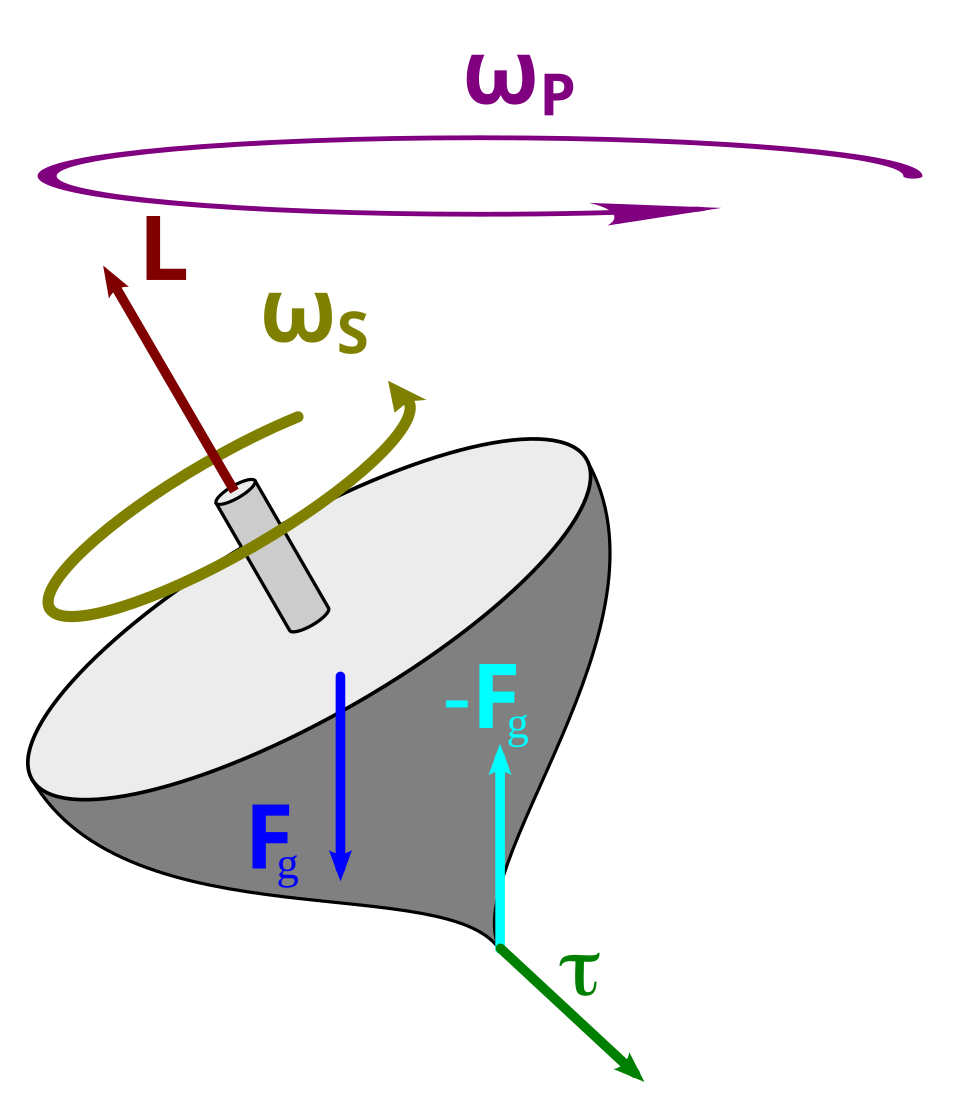 a spinning top is the cleanest example of the gyroscopic term. gravity $\mathbf{F_g}$ pulls down and makes a torque $\boldsymbol{\tau}$ (green) at a right angle to the spin axis. instead of toppling, the angular momentum $\mathbf{L}$ swings sideways and the whole top circles slowly, that purple loop $\omega_P$. exactly the same $\boldsymbol{\omega} \times \mathbf{L}$ math that shows up in our drone. figure by Xavier Snelgrove, Wikimedia Commons, CC BY-SA 2.5
And here is the same thing actually moving. Watch the spin axis slowly sweep around instead of just dropping, that slow sweep is the precession:
 a gimbal-mounted gyroscope precessing. the heavy disk spins fast, gravity tries to tip it, and the axis answers by circling. animation by Lucas Vieira, Wikimedia Commons, public domain
So when does it actually fire on our quad? Here is the satisfying payoff. Plug $I_{xx} = I_{yy}$ (true for our symmetric quad) into the cross product and most of it cancels. What survives only switches on when yaw is happening at the same time as roll or pitch, like yawing while the nose pitches down. Rotate about a single axis and the term is exactly zero (you are on a clean axis, so by Fact 1 spin and momentum already align). Roll and pitch together with no yaw also cancels, thanks to that $I_{xx} = I_{yy}$ symmetry. And in a calm hover $\boldsymbol{\omega} \approx 0$, so the whole thing is zero anyway. The one time it really bites is a violent multi-axis tumble, which is exactly the mess the RL recovery policy has to dig the drone out of, and exactly when I want the simulator telling the truth.
In code, component by component:
1
2
3
4
double Iwx = QD_IXX*s.wx, Iwy = QD_IYY*s.wy, Iwz = QD_IZZ*s.wz;
d.wx = (tau_x - (s.wy*Iwz - s.wz*Iwy)) / QD_IXX;
d.wy = (tau_y - (s.wz*Iwx - s.wx*Iwz)) / QD_IYY;
d.wz = (tau_z - (s.wx*Iwy - s.wy*Iwx)) / QD_IZZ;
First line computes the angular momentum components $I\boldsymbol{\omega}$. Then each axis gets (torque minus gyroscopic term) divided by inertia. It is the boxed equation above, unrolled by hand, no matrix library needed.
The Quaternion Part
Four derivatives left, one for each stored quaternion component: how fast is the orientation changing? We derived this in the last post, the quaternion kinematic equation:
\[\dot{\mathbf{q}} = \frac{1}{2}\,\mathbf{q}\,\boldsymbol{\omega}_q\]And here it is in the middle of qd_derivative, the Hamilton product unrolled with the $\frac{1}{2}$ sitting right there:
1
2
3
4
d.qw = 0.5*(-s.qx*s.wx - s.qy*s.wy - s.qz*s.wz);
d.qx = 0.5*( s.qw*s.wx + s.qy*s.wz - s.qz*s.wy);
d.qy = 0.5*( s.qw*s.wy - s.qx*s.wz + s.qz*s.wx);
d.qz = 0.5*( s.qw*s.wz + s.qx*s.wy - s.qy*s.wx);
When I wrote the quaternion post I called this equation the bridge between the gyro and orientation. Well, this is the bridge, in production, getting walked across 200 times a second.
The Whole Function
Put all the pieces together and here is the complete physics of a quadrotor. Thirteen numbers in, thirteen rates of change out:
1
2
3
4
5
6
7
8
9
10
11
12
13
14
15
16
17
18
19
20
21
22
23
24
25
26
27
28
29
30
31
32
33
34
35
36
37
inline QuadState qd_derivative(const QuadState &s, const std::array<double,4> &omega)
{
    // 1. motors -> thrust + torques (the mixing matrix)
    double w2[4] = {omega[0]*omega[0], omega[1]*omega[1],
                    omega[2]*omega[2], omega[3]*omega[3]};

    double thrust = QD_KT * (w2[0] + w2[1] + w2[2] + w2[3]);
    double tau_x  = QD_KT * QD_L * ( w2[1] - w2[3]);
    double tau_y  = QD_KT * QD_L * ( w2[2] - w2[0]);
    double tau_z  = QD_KQ        * (-w2[0] + w2[1] - w2[2] + w2[3]);

    // 2. rotate body-frame thrust into the world frame
    double fx, fy, fz;
    qd_quat_rot(s.qw, s.qx, s.qy, s.qz, 0.0, 0.0, thrust, fx, fy, fz);

    QuadState d;

    // 3. Newton: position and velocity
    d.px = s.vx; d.py = s.vy; d.pz = s.vz;
    d.vx = fx / QD_MASS;
    d.vy = fy / QD_MASS;
    d.vz = fz / QD_MASS - QD_GRAVITY;

    // 4. quaternion kinematics: dq/dt = 0.5 * q * omega
    d.qw = 0.5*(-s.qx*s.wx - s.qy*s.wy - s.qz*s.wz);
    d.qx = 0.5*( s.qw*s.wx + s.qy*s.wz - s.qz*s.wy);
    d.qy = 0.5*( s.qw*s.wy - s.qx*s.wz + s.qz*s.wx);
    d.qz = 0.5*( s.qw*s.wz + s.qx*s.wy - s.qy*s.wx);

    // 5. Euler: angular acceleration with gyroscopic coupling
    double Iwx = QD_IXX*s.wx, Iwy = QD_IYY*s.wy, Iwz = QD_IZZ*s.wz;
    d.wx = (tau_x - (s.wy*Iwz - s.wz*Iwy)) / QD_IXX;
    d.wy = (tau_y - (s.wz*Iwx - s.wx*Iwz)) / QD_IYY;
    d.wz = (tau_z - (s.wx*Iwy - s.wy*Iwx)) / QD_IZZ;

    return d;
}
By the way, this combo has a name you will see all over robotics papers: the Newton-Euler equations. Newton handles the translation (steps 2 and 3), Euler handles the angular acceleration (step 5), and step 4 in between is the quaternion kinematics from last post, the bookkeeping that turns angular velocity back into orientation. The first time I saw “Newton-Euler formulation” in a paper I assumed it was something terrifying. It is the function above. That’s it, that’s the formulation.
Integration: Turning Rates Into Motion
Okay. We can compute how fast everything is changing right now. But the simulator needs to answer “where is the drone 5 milliseconds from now?”, and then do that again, and again, 200 times a second forever. Going from rates to actual positions is called integration.
The Obvious Way, and Why It Slowly Lies to You
The most natural idea: if I know how fast something changes, multiply by the time step and add it on.
\[\mathbf{x}_{next} = \mathbf{x} + dt \cdot f(\mathbf{x})\]This is called the Euler method (him again!) and it is beautifully simple and subtly wrong. It assumes the rate of change stays constant for the entire step. It is like driving while only looking at the road once every 5 milliseconds and steering in a perfectly straight line in between. On a straight road, fine. In a corner, you drift wide on every single look, always to the outside, and the errors all push the same direction so they pile up instead of canceling.
For a drone this is bad news specifically because of all the rotation. A hovering drone wobbling gently is full of oscillating, curving quantities, and the Euler method systematically overshoots curves. The classic symptom: energy slowly creeps into the system out of nowhere, oscillations grow instead of staying steady, and after a couple of minutes your perfectly tuned hover is mysteriously vibrating itself apart. The physics is not unstable, your integrator is.
RK4: Look Before You Leap, Four Times
The fix my sim uses is the classic fourth order Runge-Kutta method, RK4 to its friends. The idea is almost embarrassingly sensible: instead of sampling the slope once at the start and committing, sample it four times across the step and take a weighted average.
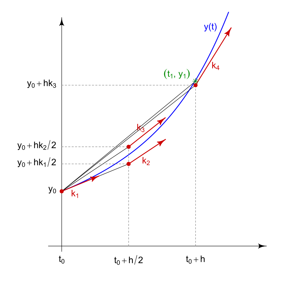 the four slope samples of one RK4 step. figure by HilberTraum, Wikimedia Commons, CC BY-SA 4.0
- $k_1$: slope at the start of the step (this alone is the Euler method)
- $k_2$: walk half a step using $k_1$, sample the slope there
- $k_3$: walk half a step using $k_2$ instead, sample again (a midpoint estimate informed by another midpoint estimate, this is the subtle one)
- $k_4$: walk the full step using $k_3$, sample the slope at the far end
Then blend them, midpoints weighted double:
\[\mathbf{x}_{next} = \mathbf{x} + \frac{dt}{6}\left(k_1 + 2k_2 + 2k_3 + k_4\right)\]Why bother? Accuracy per step. Halve the time step and the Euler method’s total error halves. Halve the time step with RK4 and the total error drops by a factor of sixteen. At 200 Hz with RK4 the integration error in this sim sits orders of magnitude below the simulated sensor noise, so in practice the sensors are always the thing I worry about, never the integrator. The cost is calling qd_derivative four times per step instead of once, and that function is all cheap multiply-adds, so it is nothing.
Here is my implementation:
1
2
3
4
5
6
7
8
9
10
11
12
13
14
15
16
17
18
19
20
21
22
23
24
25
26
inline QuadState qd_rk4(const QuadState &s, const std::array<double,4> &omega, double dt)
{
    auto axpy = [](const QuadState &a, const QuadState &b, double h) -> QuadState {
        QuadState r;
        r.px = a.px+h*b.px; r.py = a.py+h*b.py; r.pz = a.pz+h*b.pz;
        r.vx = a.vx+h*b.vx; r.vy = a.vy+h*b.vy; r.vz = a.vz+h*b.vz;
        r.qw = a.qw+h*b.qw; r.qx = a.qx+h*b.qx;
        r.qy = a.qy+h*b.qy; r.qz = a.qz+h*b.qz;
        r.wx = a.wx+h*b.wx; r.wy = a.wy+h*b.wy; r.wz = a.wz+h*b.wz;
        return r;
    };

    QuadState k1 = qd_derivative(s,              omega);
    QuadState k2 = qd_derivative(axpy(s,k1,dt/2),omega);
    QuadState k3 = qd_derivative(axpy(s,k2,dt/2),omega);
    QuadState k4 = qd_derivative(axpy(s,k3,dt),  omega);

    QuadState next;
    #define F(f) next.f = s.f + (dt/6)*(k1.f + 2*k2.f + 2*k3.f + k4.f)
    F(px);F(py);F(pz); F(vx);F(vy);F(vz);
    F(qw);F(qx);F(qy);F(qz); F(wx);F(wy);F(wz);
    #undef F

    qd_normalize(next);
    return next;
}
A few things worth pointing out:
- The little
axpylambda computesa + h*bfield by field. The name is an old BLAS joke, “a x plus y”, that linear algebra people have been using since the 70s. My state is a plain struct instead of a vector type, so I spelled it out by hand. - Notice
omega(the motor speeds) is the same in all four calls. We assume the motors hold constant for the whole 5 ms step. The controller only updates them once per tick anyway, so nothing is lost. - The
#define F(...)macro is me refusing to write that weighted sum thirteen times. Some people hate macros in C++, in a 13-field struct sum I think it is the most readable option.
Then Renormalize, Always
The very last line, qd_normalize(next), matters more than its size suggests. RK4 treats our quaternion as just 4 independent floats, it has no idea they are supposed to satisfy $|\mathbf{q}| = 1$. So every step nudges the norm a tiny bit off unit length, and a non-unit quaternion does not just rotate, it scales. Leave it unchecked and your drone slowly inflates. We covered the fix in the quaternion post: one square root, four divides, every step, problem gone forever.
The Loop That Runs It All
Everything above lives in a header. The actual ROS 2 node that uses it is almost anticlimactic:
1
2
3
4
5
6
7
8
9
10
11
12
13
void step()
{
    state_ = qd_rk4(state_, motors_, DT);   // DT = 0.005, the whole physics

    if (state_.pz < 0.0) {                  // crude ground collision
        state_.pz = 0.0;
        state_.vx = state_.vy = state_.vz = 0.0;
        ...
    }

    publish_odom();    // 13 numbers out as a ROS Odometry message
    publish_imu();     // fake gyro + accelerometer with realistic noise
}
A timer fires this every 5 milliseconds, 200 Hz. One line of physics, then housekeeping. The motor speeds in motors_ arrive on a ROS topic from the PID controller, which closes the loop: controller picks motor speeds, physics moves the drone, sensors report back, controller reacts.
About that collision check, yes, my ground physics is literally “if you are below the floor, you are now on the floor and you have stopped”. Real contact dynamics is a deep and genuinely hard field and none of it matters for learning flight control, so the floor in my world is perfectly sticky and the crash is a log message. There is a wall at x = 3 m with the same treatment (it exists so the RL recovery policy has something to be thrown at, a story for another post).
The IMU publishing in that loop is its own rabbit hole, datasheet noise densities, bias random walk, why the accelerometer reads gravity upward, and it ties straight into the ADIS16470, an actual sensor from the company whose interview I am preparing for. Next post.
Wrap Up
The TLDR of the whole post:
- The drone is fully described by 13 numbers: position, velocity, quaternion, angular velocity. Physics is one function that maps these 13 numbers to their 13 rates of change.
- A propeller does two things, thrust ($K_T\omega^2$, air pushed down) and reaction torque ($K_Q\omega^2$, body twisted opposite to the prop).
- The mixing matrix turns 4 motor speeds into thrust + roll/pitch/yaw torques. Thrust differences steer roll and pitch, spin-direction imbalance steers yaw. Counter-rotating pairs are why quads need no tail rotor.
- Newton’s half: rotate thrust into the world frame (quaternion sandwich), add gravity, divide by mass.
- Euler’s half: torque over inertia, plus the gyroscopic term $\boldsymbol{\omega} \times (I\boldsymbol{\omega})$ that only wakes up when yaw mixes with roll or pitch. Moment of inertia is rotational mass and it depends on the axis, which is why $I_{zz} \approx 2 I_{xx}$ on a quad.
- RK4 integration samples the slope four times per step and weights the midpoints double. Errors shrink 16x when you halve the step, versus 2x for the naive method.
- Renormalize the quaternion after every step, the integrator does not know about the unit constraint.
If I have done my job, the phrase “Newton-Euler dynamics with RK4 integration” now sounds like what it is, one honest function and a careful way of adding.
Further Reading
- Andrew Gibiansky, Quadcopter Dynamics and Simulation, the classic blog post on this exact topic, with a full derivation and MATLAB code. I cross-checked my mixing matrix signs against this more than once.
- Percy Jaiswal, Demystifying Drone Dynamics, same article I borrowed the frames figure from in post one, covers the dynamics with nice visuals.
- Wikipedia, Runge-Kutta methods, goes much deeper into why the 1-2-2-1 weighting works, including the general Butcher tableau if you want to see RK4’s whole extended family.
Thanks for reading, this one was heavy on physics, so if I got anything wrong pls ping me on X and I will fix it.