Why Can't a Drone Trust Its Own Sensors?
What an IMU actually measures, why a still drone feels gravity pushing up, and why noise, bias and drift mean a drone can never fully trust its own sensors.
Imagine you are blindfolded, sitting in a chair with wheels, and someone is slowly pushing you around an dark room. Could you tell where you are? For the first few seconds, kind of. You feel the pushes, you feel yourself turning, and in your head you try to keep track of “ok I went forward a bit, then turned left”. But after a minute? You are completely lost. Your sense of every little push has added up into one big guess, and the guess has drifted away from the truth.
That blindfolded person is my drone. Indoors there is no GPS, so the drone has no outside reference for where it is or which way it is pointing. The only thing it has is a tiny sensor called the IMU, bolted to its body, whispering “this is how fast you are spinning, this is how hard you are being shoved”. And here is the uncomfortable truth this whole post is about: that sensor is lying to the drone. A little, constantly, and in a way that adds up.
So the question is, why can’t the drone just trust what it feels? Lets find out.
Where we are in the series. Post one was coordinate frames (world frame vs body frame). Post two was quaternions. Post three built the physics that moves the drone. This post is about the sensors that try to measure that motion, and why they are harder to trust than you would think.
What Is Even Inside an IMU?
IMU stands for Inertial Measurement Unit. It is a little chip, smaller than your fingernail, and it lives on basically every drone, every phone, and every VR headset. Inside it there are really just two sensors that matter for us.
The gyroscope measures how fast the drone is rotating, in radians per second, around each of its own body axes. Roll rate, pitch rate, yaw rate. In my simulator’s state these are the three numbers wx, wy, wz from last post.
The accelerometer measures acceleration, in meters per second squared, along each of the drone’s body axes. How hard, and in what direction, the drone is being shoved.
Both of these measure things in the body frame, the frame glued to the drone, like we talked about in this post. The gyro cannot feel “north”, it can only feel “I am rotating about my own nose-axis”. That detail matters more than it sounds, and the accelerometer is about to prove it in the weirdest way.
The Weird Part: A Still Drone Feels Gravity Pushing Up
Here is a question thats wiered to understand , like question itself feels senseless tbh.
The drone is sitting perfectly still on the ground. Not moving, not tilting, nothing. What does its accelerometer read?
Your common sense says zero, right? It is not accelerating, so acceleration is zero. Makes sense.
Wrong. It reads about 9.81 m/s², pointing straight up. A full $g$ of acceleration, upward, while sitting completely still. but why?
Ok so here is the trick, and once it clicks you never forget it. An accelerometer does not measure “am I speeding up”. It measures something physicists call proper acceleration, but I find it way easier to think of it as “what is physically pushing on me right now”.
Think about standing in an elevator :
- Elevator still, or moving at constant speed : you feel your normal weight. The floor is pushing up on your feet with enough force to hold you against gravity.
- Elevator shoots up : you feel heavier, your knees bend a little. The floor is pushing harder , its like You feel the gravity.
- Elevator drops (the stomach-lurch moment) : you feel lighter. The floor pushes less.
- The cable snaps and you are in free fall : you feel weightless. Nothing is pushing on you at all ( and die so u eventully feel nothing lol ).
Now notice the punchline. You feel weightless during free fall, the one moment you are actually accelerating the most (straight down at $g$). And you feel your full weight when you are sitting completely still. An accelerometer feels the exact same thing you do. It does not report how the ground sees you move, it reports the force holding it up.
So a drone resting on the ground has the ground pushing up on it at $g$ to stop it falling, and the accelerometer faithfully reports that upward push : $+9.81$ on the body z axis. A drone in free fall would read zero on all axes, even though it is plummeting. Backwards from your intuition, completely correct.
In my simulator’s standalone IMU node, with the drone sitting still, the code just hard-codes this :
1
2
3
4
5
// Stationary robot: accelerometer measures reaction against gravity.
// Body frame Z points up  ->  az = +9.81 m/s^2
msg.linear_acceleration.x = accel_bias_[0] + accel_noise_(rng_);
msg.linear_acceleration.y = accel_bias_[1] + accel_noise_(rng_);
msg.linear_acceleration.z = 9.81 + accel_bias_[2] + accel_noise_(rng_);
Ignore the bias and noise for a second (I’ll explain later in this post). The important line is z = 9.81. Still drone, gravity reads up.
But that is only true when the drone is flat. The moment it tilts, “up for the drone” stops being “up in the world”, and we have to rotate gravity into the body frame to figure out what the accelerometer should feel. That is the quaternion trick from post one and post three :
1
2
qd_quat_rot(state_.qw, -state_.qx, -state_.qy, -state_.qz,
            0.0, 0.0, QD_GRAVITY, ax, ay, az);
Those minus signs build the conjugate of the orientation quaternion, which rotates the world’s gravity vector into the body frame. If the drone is tilted 30 degrees, the accelerometer feels gravity smeared across two axes instead of pointing cleanly down its z. This is genuinely useful, because it means the accelerometer secretly knows which way is down, which is going to matter a lot in the next post. Hold that thought.
Every Sensor Lies, Here Is The Formula
Ok so now the main event. In a perfect world, a sensor reading would just be the true value. In the real world, every sensor reading is actually this :
\[\text{measurement} = \text{true value} + \text{bias} + \text{noise}\]Three pieces. The true value is what you wish you were getting. The other two are the lies. So for the rest of this post, we only need to understand two words : noise and bias.
Let me take them one at a time, starting with noise.
Noise: The Constant Jitter
Noise is the random jitter sitting on top of every single reading. Even if the drone is bolted to a table in a quiet room, the gyro will not read a clean zero. It reads a tiny bit positive, then a tiny bit negative, then positive, jittering around the truth thousands of times a second. This comes from the physics of the tiny vibrating structures inside the chip, from heat, from the electronics. You cannot get rid of it. Every sensor has it.
The good news is this jitter is random in a very well behaved way. If you record a stationary sensor for a while and plot how often each reading shows up, you get the famous bell curve :
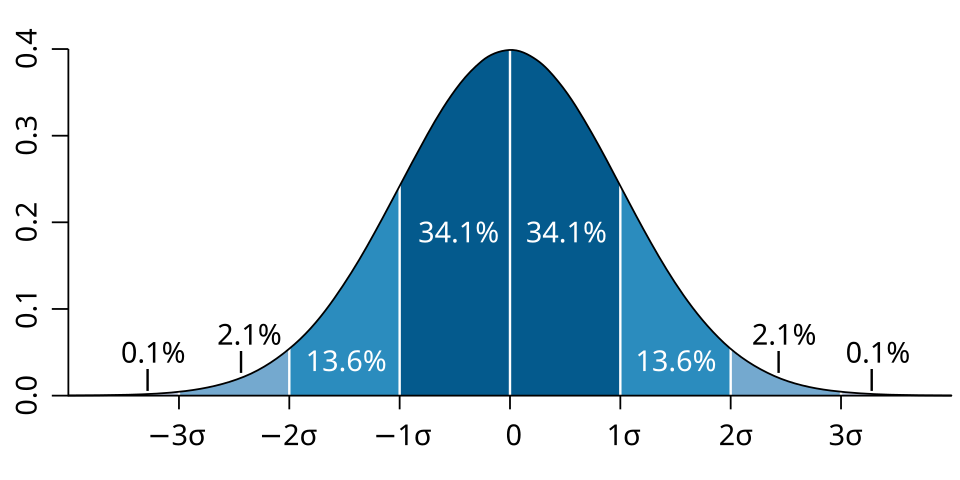 the bell curve (Gaussian / normal distribution). most readings land close to the true value in the middle, big errors are rare. about 68% of readings fall within one sigma, 95% within two. figure by M. W. Toews, Wikimedia Commons, CC BY 2.5
This shape is called a Gaussian (or normal) distribution, and it shows up everywhere in nature when lots of tiny random effects add together. The middle of the bump is the true value. Most readings land close to it. The further out you go, the rarer the error. The width of the bump is measured by one number, the standard deviation, written $\sigma$ (sigma). Small $\sigma$ means a tall thin bump and a precise sensor. Big $\sigma$ means a wide bump and a noisy one.
This is so standard that simulating it is a one liner. In my IMU code the noise is just a draw from a Gaussian with mean 0 :
1
2
3
std::normal_distribution<double> gyro_noise_, accel_noise_;
// ...
msg.angular_velocity.x = gyro_bias_[0] + gyro_noise_(rng_);
gyro_noise_(rng_) literally rolls the dice on that bell curve (picking random number) every time the sensor publishes, and adds the result. Mean zero, so on average it cancels out. But on any single reading, it is wrong by some random amount. The size of that amount is $\sigma$, Now we need to figure out how to choose a realistic value for $\sigma$
The Weirdest Units You Will See: rad/s/√Hz
If you pull up the datasheet for a real IMU and look for the noise spec, you will not find a nice number like “the gyro noise is 0.01 rad/s”. Instead you find something that looks like a typo :
\[0.16 \; \text{deg}/\sqrt{\text{hr}} \qquad \text{or} \qquad 4.65 \times 10^{-4} \; (\text{rad/s})/\sqrt{\text{Hz}}\]Degrees per square root of an hour? What does a square root of an hour even mean? This confused me a lot, so here is the plain English version.
The spec is not the noise itself, it is the noise density. The reason they give a density instead of a flat number is that how much noise you actually see depends on how fast you sample the sensor.
Here is the intuition. Imagine taking a photo of a hummingbird’s wings. A slow camera (long exposure) blurs all the fast motion together into a smooth average, so the wings look calm. A super fast camera (tiny exposure) freezes each instant, so you catch all the rapid jitter. The faster you sample, the more of the high-speed jitter you actually capture.
Sensors are the same. Sample the gyro 10 times a second and each reading is a relatively calm average. Sample it 1000 times a second and each reading catches much more of the raw jitter. So the manufacturer cannot print one noise number, because it would be different for every customer. Instead they give a density, and you convert it to a real $\sigma$ once you know your own sample rate, using :
\[\sigma = \text{density} \times \sqrt{\text{sample rate}}\]The square root is why the units have that $\sqrt{\text{Hz}}$ in them, it is built so that this multiplication comes out with clean units. My sim samples at 200 Hz, so that is what the code does :
1
2
3
// Scale noise density to 200 Hz sample rate: sigma = density * sqrt(sample_rate)
gyro_noise_ (0.0, GYRO_ARW   * std::sqrt(200.0)),
accel_noise_(0.0, ACCEL_VRW  * std::sqrt(200.0)),
GYRO_ARW is the density straight off the datasheet, the $\sqrt{200}$ turns it into the actual standard deviation of the jitter at my sample rate. That is the $\sigma$ that goes into the bell curve.
Random Walk: Why Noise That Averages To Zero Still Ruins You
Now here is a thing that sounds contradictory. I just said the noise has mean zero, so it averages out. So who cares, right? If it cancels out on average, it should not hurt.
It hurts because of what the drone does with the gyro reading. The gyro tells you a rotation rate. To know the drone’s actual angle, you have to add up (integrate) all those rates over time. And when you add up a bunch of random numbers, even ones centered on zero, you do not get zero. You get a random walk.
A random walk is the path you trace if you take a step in a random direction, then another, then another. Each step is tiny and unbiased, but the sum wanders away from where it started and basically never comes back :
 a random walk. each step is small and random with no preferred direction, yet the path still drifts further and further from the start over time. this is what happens to an angle estimate when you keep adding up noisy gyro readings. figure by László Németh, Wikimedia Commons, public domain (CC0)
This is the blindfolded-chair problem from the intro, made precise. Each individual gyro reading is only a hair off. But you are adding thousands of them per second to track your angle, and those tiny errors accumulate into a slow, drunken drift in the drone’s idea of which way it is pointing. Leave a perfectly good gyro integrating on a table for ten minutes and it will swear it has rotated by some real angle, having never moved at all.
This effect is so central that the gyro’s noise spec is literally named after it : Angular Random Walk, or ARW (that is what GYRO_ARW stands for in my code). It is a slightly confusing name, it describes the white noise on the rate, but it is named for the random walk that noise causes in the integrated angle. The accelerometer has the exact same story one level up : its spec is Velocity Random Walk (VRW), because integrating noisy acceleration gives you a random walk in velocity.
So that is lie number one : noise, which feels harmless because it averages to zero, but quietly poisons anything you integrate.
Bias: The Lie That Does Not Even Try To Average Out
Noise at least has the decency to be centered on the truth. Bias does not.
Bias is a constant (ish) offset. The sensor just reads a bit high, or a bit low, all the time. Picture a kitchen scale that shows 50 grams even when it is empty. Every single thing you weigh on it is now 50 grams too heavy. Averaging more readings does not help one bit, because they are all wrong in the same direction.
For a gyro, a bias means the drone thinks it is slowly rotating even when it is rock still. And remember what we do with gyro readings, we integrate them. Integrating a constant bias does not give you a gentle random walk, it gives you a straight-line error that grows and grows, fast. A tiny constant bias is far more destructive to your angle estimate than a much larger dose of zero-mean noise.
And it gets one notch worse, because bias is not even truly constant. It drifts slowly over time as the chip warms up and ages. The standard way to model that slow drift is, of all things, another random walk, a really slow one laid on top of the bias itself. My sim does the same thing, nudging the bias by a tiny random amount on every step :
1
2
3
4
5
// Bias drifts slowly each step (random walk)
for (int i = 0; i < 3; ++i) {
    gyro_bias_[i]  += gyro_bwalk_(rng_);
    accel_bias_[i] += accel_bwalk_(rng_);
}
So now you can see the full picture of the lie. The reading you get is the true value, plus a slowly wandering bias, plus a fresh dollop of bell-curve noise, every single time :
1
2
msg.angular_velocity.x    = state_.wx + gyro_bias_[0]  + gyro_noise_(rng_);
//                          ^ truth     ^ slow drift      ^ random jitter
That one line is the entire “every sensor lies” formula from earlier, written in C++.
So Where Did My Sim’s Numbers Come From?
Fair question, since I have been throwing constants like GYRO_ARW = 4.65e-4 around. I did not make them up. I pulled them from the datasheet of a real MEMS IMU (I used Analog Devices’ ADIS16470) and dropped the published noise densities straight into the code :
1
2
3
4
static constexpr double GYRO_ARW    = 4.65e-4;   // rad/s/sqrt(Hz)
static constexpr double ACCEL_VRW   = 1.03e-3;   // m/s^2/sqrt(Hz)
static constexpr double GYRO_BIAS_WALK  = 1.0e-6; // rad/s per step
static constexpr double ACCEL_BIAS_WALK = 5.0e-5; // m/s^2 per step
The point of using real datasheet values is that the fake sensor in my simulator misbehaves with roughly the same personality as the real chip would. If my flight code can survive this noise and drift in sim, it has a fighting chance on real hardware. A simulator that gives you perfect, clean sensor readings is lying to you, the engineer, way worse than any real sensor ever could.
Bonus, how do engineers even measure these numbers? There is a neat tool called the Allan variance. You log a sensor sitting still for a few hours, then look at how the averaged reading wanders over different time windows. Short windows expose the white noise, long windows expose the bias drift, and the shape of the curve lets you read off each noise source separately. That is how a datasheet ends up with an ARW number in the first place. Worth a look if you ever have to characterise a real sensor.
So Both Sensors Lie. Now What?
So, why can’t a drone trust its own sensors? Because every reading is the true value with noise and bias added on top, and the moment you integrate to get a useful quantity like angle or velocity, those small errors snowball into real drift.
Quick recap of the lies :
- Noise is zero-mean bell-curve jitter on every reading. Harmless looking, but integrate it and you get a slow random walk (ARW for the gyro, VRW for the accel).
- Bias is a near-constant offset that does not average out, and it drifts slowly on top of that. Integrate it and your error grows in a straight line. This is the real killer.
- The datasheet hands you noise densities, which you scale by $\sqrt{\text{sample rate}}$ to get the actual $\sigma$.
- An accelerometer measures the force holding it up, which is why a still drone feels $g$ pushing up and a falling drone feels nothing.
But here is the hopeful bit, and the reason the next post exists. The two sensors are bad at different things :
- The gyro is smooth and trustworthy over a fraction of a second, but drifts over seconds and minutes.
- The accelerometer is noisy moment to moment, but it never drifts, because it always has gravity as an absolute “this way is down” reference (remember, it secretly knows which way is down).
One is useful where the other is weak. So what if you could blend them, trusting the gyro for the quick stuff and gently correcting its drift using the accelerometer’s long-term honesty? You can. The tool that does it is called a Kalman filter, and figuring out how it fuses two lying sensors into one estimate you can actually trust is the whole next post.
Thanks for reading, this one was all about why sensors are honest liar, so if I got anything wrong pls ping me on X and I will fix it.